
This is a post by Andrew K.
Posted Wednesday, July 3, 2024
My first entry into create a Raspberry PI HAT
This is a post by Andrew K.
Posted Wednesday, July 3, 2024
Over the last 12 months I had been looking at building a hydroponics set up using the Raspberry PI. I wanted a cost effective and repairable solution for handling soil/moisture measurements.
There of course many HATs already available which solve many problems, but after quite a bit of research found that the HATs available severly restricted the capability of the PI and increased costs should I ever want to scale up.
I initially started very simply by looking at some of the solutions available and found several options, the simplest was this module Gravity: I2C ADS1115 16-Bit ADC Module
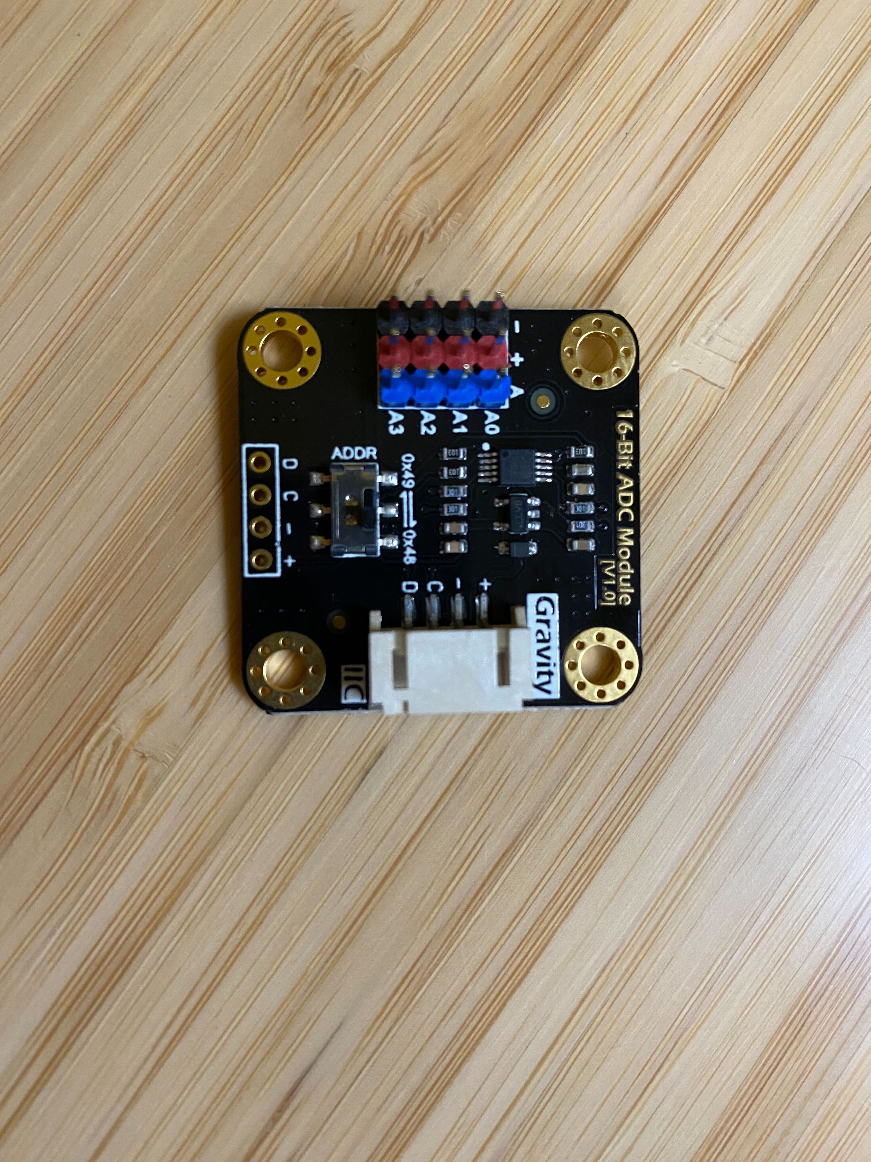
It is not too expensive, although buying multiple soon adds up. It can service 4 analogue inputs and you can put up to 4 ( two I2C bus on the Raspberry PI and two per bus ).
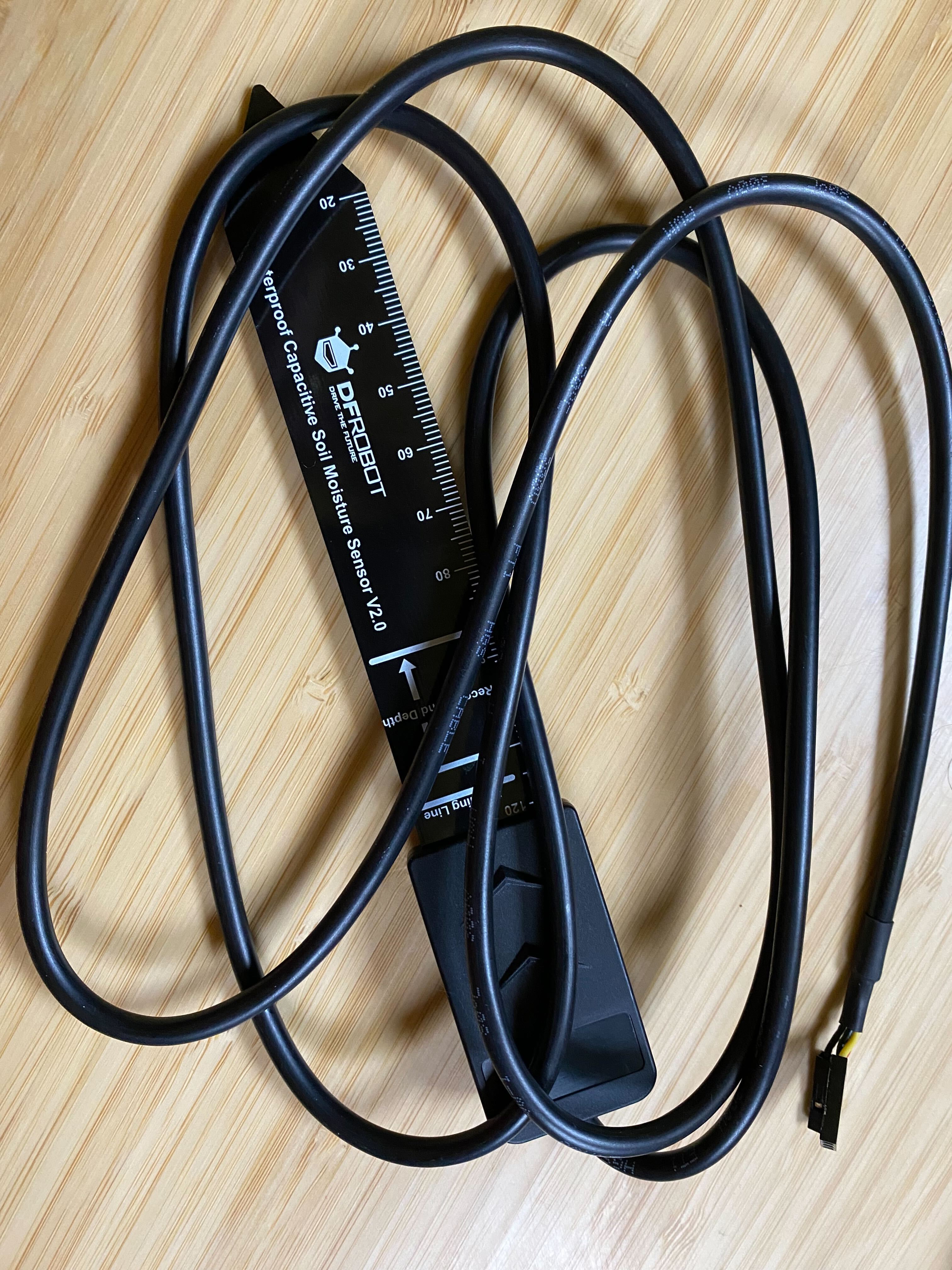
I did also purchase this sensor Gravity: Analog Waterproof Capacitive Soil Moisture Sensor
This works very well and I can get measurements from the sensor, some work is required for calibration but that is expected.
After some more research I also found several modules using the MCP3008 IC. This is an 8 channel, 10 bit, SPI package.
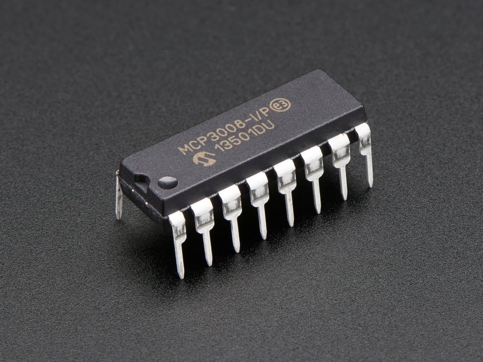
There are several Raspberry PI hats that use this package, the MCP3008 Specifications are straight forward along with penty of example code to drive it. It does have advantages over other interfaces, however it is restricted to 10bit resolution, but for the purposes of soil moisture measurements this is not an issue.
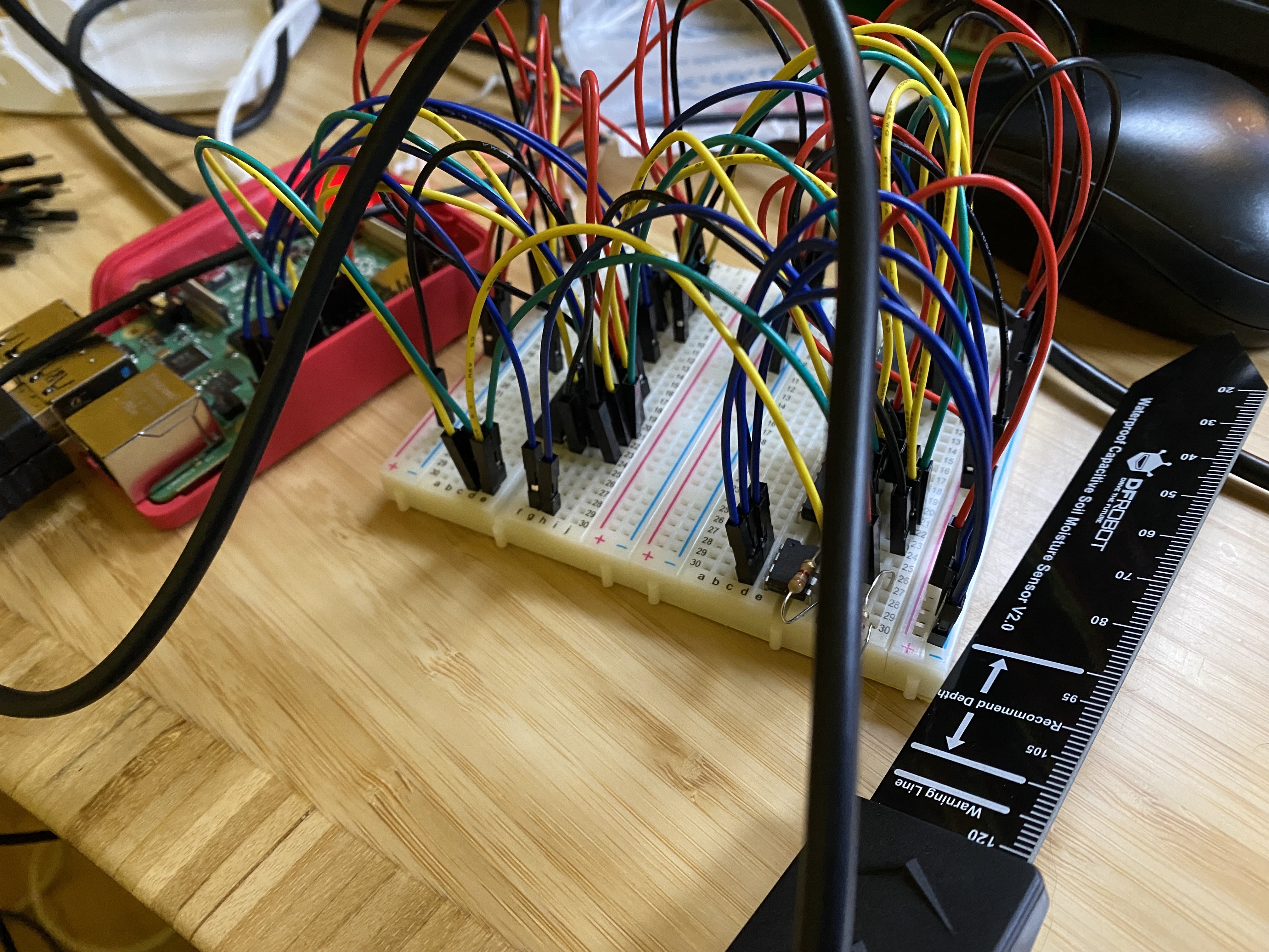
The MCP3008 is very simple to get going and to test my idea of getting more than one integrated I build a prototype on a breadboard
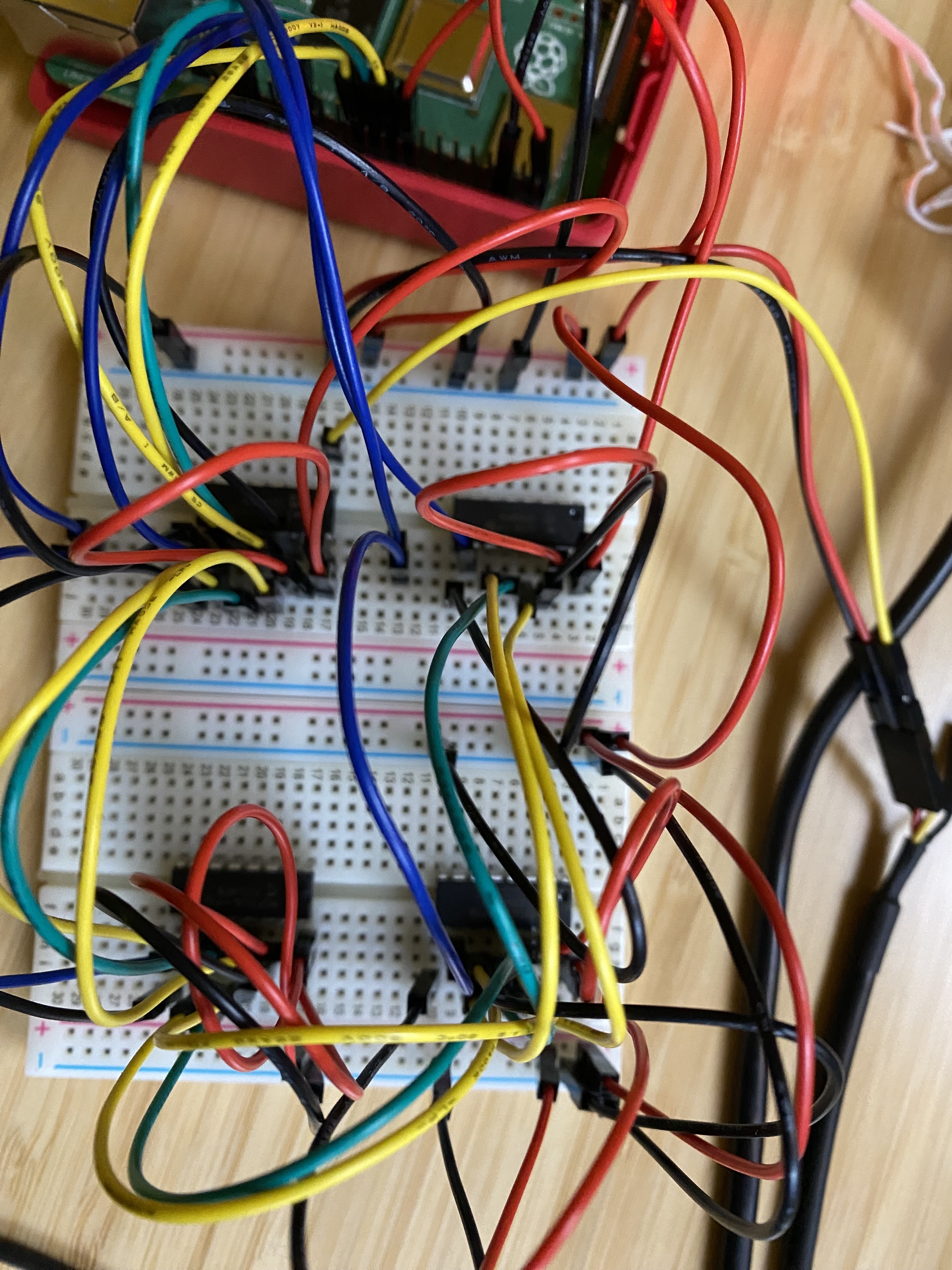
The SPI interface is daisy chained from one device to another, and separate GPIO pins on the Raspberry PI are used for selecting which IC should provide data.
The amazing people at Adafruit have a simple demo to get it going and I will post the demo code I used below.
import time
import busio
import digitalio
import board
import adafruit_mcp3xxx.mcp3008 as MCP
from adafruit_mcp3xxx.analog_in import AnalogIn

spi = busio.SPI(clock=board.SCK, MISO=board.MISO, MOSI=board.MOSI)
cs = digitalio.DigitalInOut(board.D5)

mcp = MCP.MCP3008(spi,cs)
#
channel = AnalogIn(mcp,MCP.P0)
#
while True:
    print ("Raw ADC Value: ", channel.value)
    print ("ADV Voltage: " +str(channel.value)+"V")
    time.sleep(1)
The simple thing to note is the CS definition which allows you to put the chip select on different GPIOs for different packages. Each input for each package selected is done with the line In the above there is 1 second delay between readings and for our purposes is good to see instant changes.
channel = AnalogIn(mcp,MCP.P0)
By changing this from MCP.P0 to MCP.P1 you get channel one, up to P7 to the last channel , so 0 to 7.
I then tested this with the moisture sensor I already had and it provided a simple interface which worked well.
Now I have a prototype working, whats next ?
To make this something more useable in the real world I did needed to make this into a Raspberry PI Hat. At first glance this seemed simple enough, taking the connection schematic and then producing a layout to match the correct form factor.
The Raspberry PI Hat specification suggests (is optional) to have an ID for your Hat. I had never done this before, so I thought this would be a good opportunity to see what this is about.
The simplest guide for doing this I found by MadeByMikal. It notes the gotchas and although does use a slightly more expensive EEPROM it works well.
After you have read the guide, the file you are looking at is eeprom_settings.txt. These are the following values I used
product "32 Channel ADC"
product_id 0x0001
product_ver 0x0001
vendor "Leigh Hack Space - https://leighhack.org"
The one element I use which is not covered is the custom data and I took some text and added it as hex.
The text I added was
This is a 32 channel ADC using the library found here

https://learn.adafruit.com/mcp3008-spi-adc/python-circuitpython

It uses serial SPI0 and GPIO lines 5, 6, 26 and 16 for control
I then used a text to hex converter to generate the hex information needed, and it became
custom_data
54 68 69 73 20 69 73 20 61 20 33 32 20 63 68 61 6e 6e 65 6c 20 41 44 43 20 75 73 69 6e 67 20 74 68 65 20
6c 69 62 72 61 72 79 20 66 6f 75 6e 64 20 68 65 72 65 0a 0a 68 74 74 70 73 3a 2f 2f 6c 65 61 72 6e 2e 61
64 61 66 72 75 69 74 2e 63 6f 6d 2f 6d 63 70 33 30 30 38 2d 73 70 69 2d 61 64 63 2f 70 79 74 68 6f 6e 2d
63 69 72 63 75 69 74 70 79 74 68 6f 6e 0a 0a 49 74 20 75 73 65 73 20 73 65 72 69 61 6c 20 53 50 49 30 20
61 6e 64 20 47 50 49 4f 20 6c 69 6e 65 73 20 35 2c 20 36 2c 20 32 36 20 61 6e 64 20 31 36 20 66 6f 72 20
63 6f 6e 74 72 6f 6c
end
I added this to the breadboard
Now when I went into the hat location on the file system I get
/proc/device-tree/hat $ more *
::::::::::::::
custom_0
::::::::::::::
This is a 32 channel ADC using the library found here

https://learn.adafruit.com/mcp3008-spi-adc/python-circuitpython

It uses serial SPI0 and GPIO lines 5, 6, 26 and 16 for control
::::::::::::::
name
::::::::::::::
hat
::::::::::::::
product
::::::::::::::
32 Channel ADC
::::::::::::::
product_id
::::::::::::::
0x0001
::::::::::::::
product_ver
::::::::::::::
0x0001
::::::::::::::
uuid
::::::::::::::
f9768a88-e105-4ee1-adc1-36fa5602df09
::::::::::::::
vendor
::::::::::::::
Leigh Hack Space - https://leighhack.org
In order to design a PCB for the Hat I chose to use KiCAD. I have used it before and although takes a little practise is good for someone (like me) who just wants something simple and files can be exported to various PCB manufacturers without much pain.
There are various Raspberry PI Hat designs available however many appear to be either corrupt, old or just ‘good enough’, so when you use the KiCAD checking tool it flagged lots of errors. The dimensions of the various Hat sizes can be found here so it was straight forward to create something which matched what I needed.
As part of the ethos of useability, upgradability, repairability and of course cost I chose to make all the IC locations to be sockets rather than solder in components. This then allows anyone else to decide if they want the ID EEPROM, and use all 32 channels, so adding 8 channels at a time if needed.
The only part that would be fixed are 2 x 3.9k resistors, which are only required if the EEPROM is being used. They are designed as 1/6W, but perhaps they should have been 1/4W to make it more general.
The PCB design I ended up with is
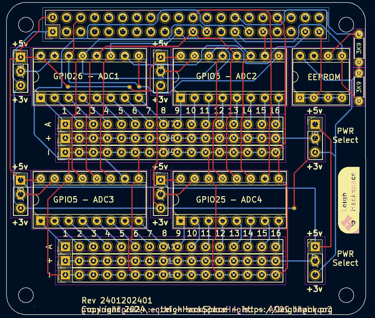
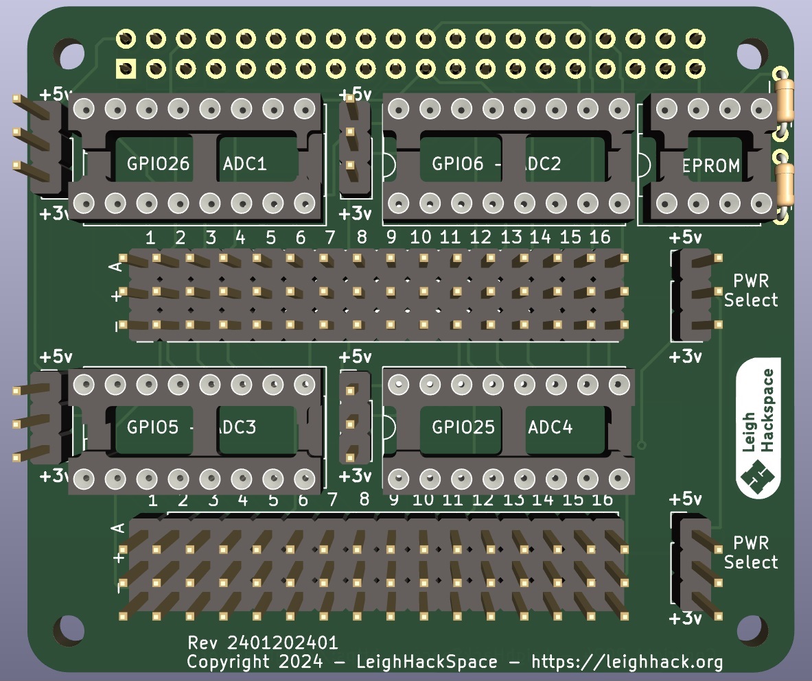
The KiCAD rendering suggested it should be ok once created with all the parts
At this point I got the PCB made from PCBWay and decided although I could just get 5 made, based on the shipping cost and the differential I had some panelized to be more efficient and also they can be bought from the HackSpace either as bare boards or finished products (tbd).
I bought all the parts needed along with stackable headers for the Hat, so when the boards can back it was time to soldering it all up.
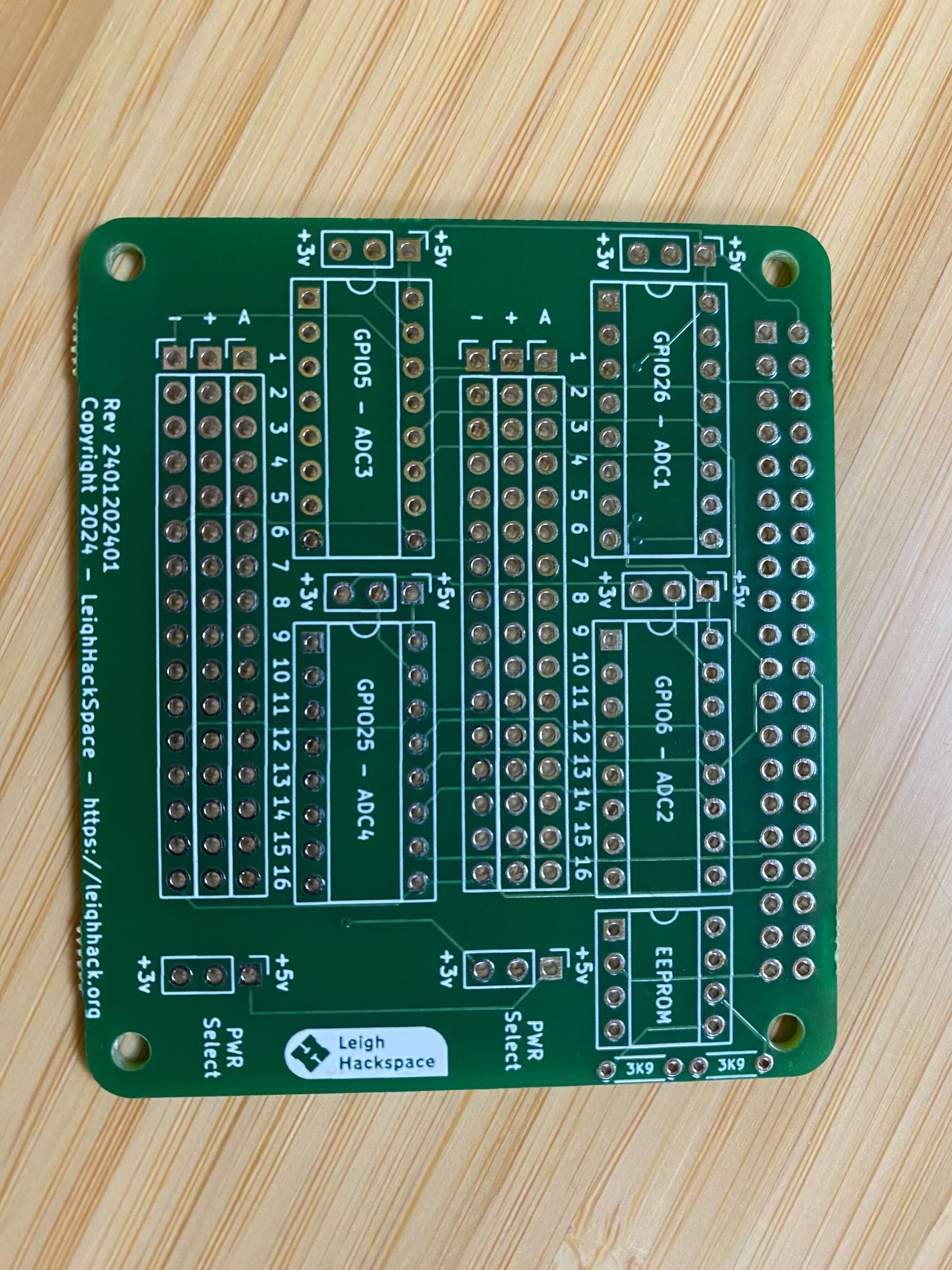
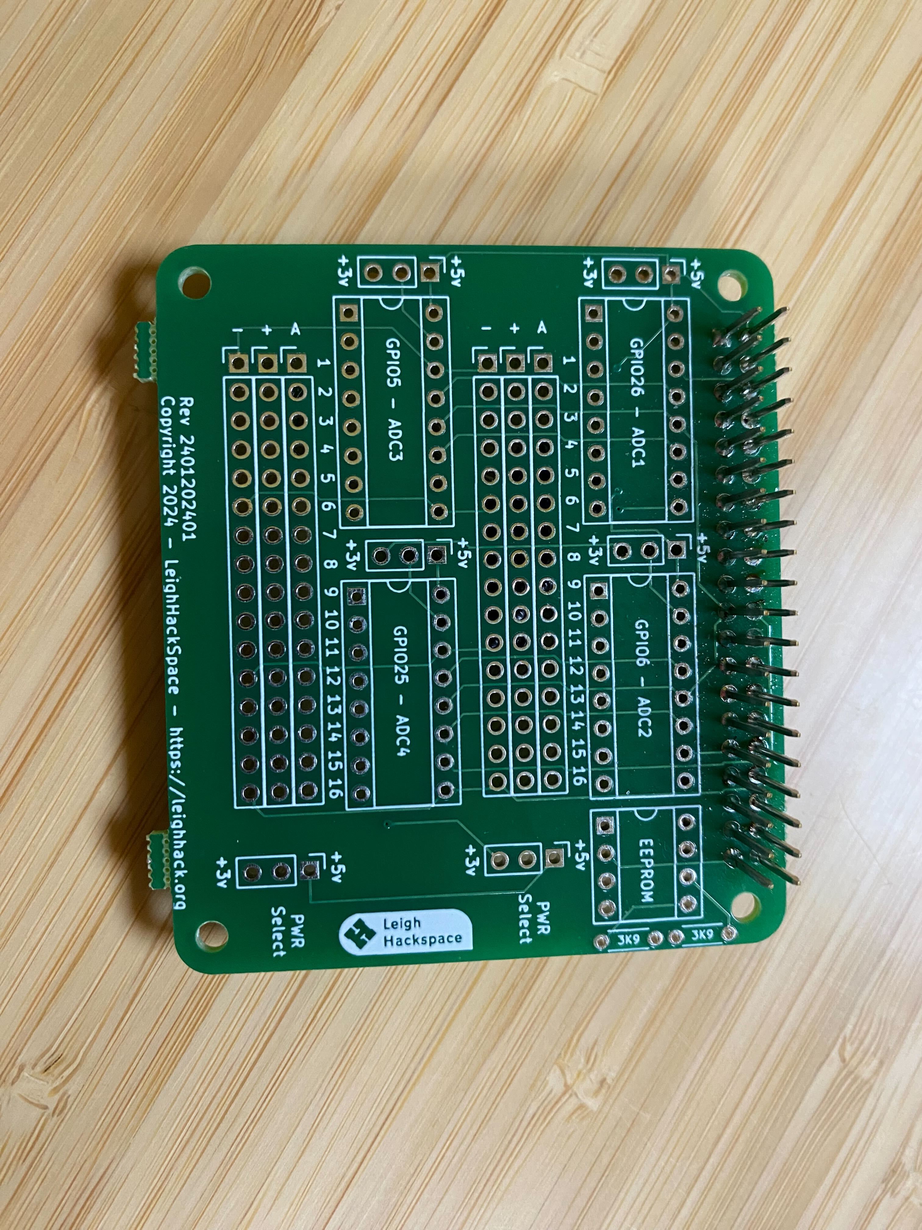
A single bare board looks like this. As you can see, and from the PCB design, I added text to the boards to show which IC is controlled by which GPIO on the Raspberry PI, just to help with deployment.
A simple gotcha was to solder the GPIO header FIRST. I went through a board figuring that one out, thankfully it was just IC sockets and was more painfully to remove than just throw away the board.
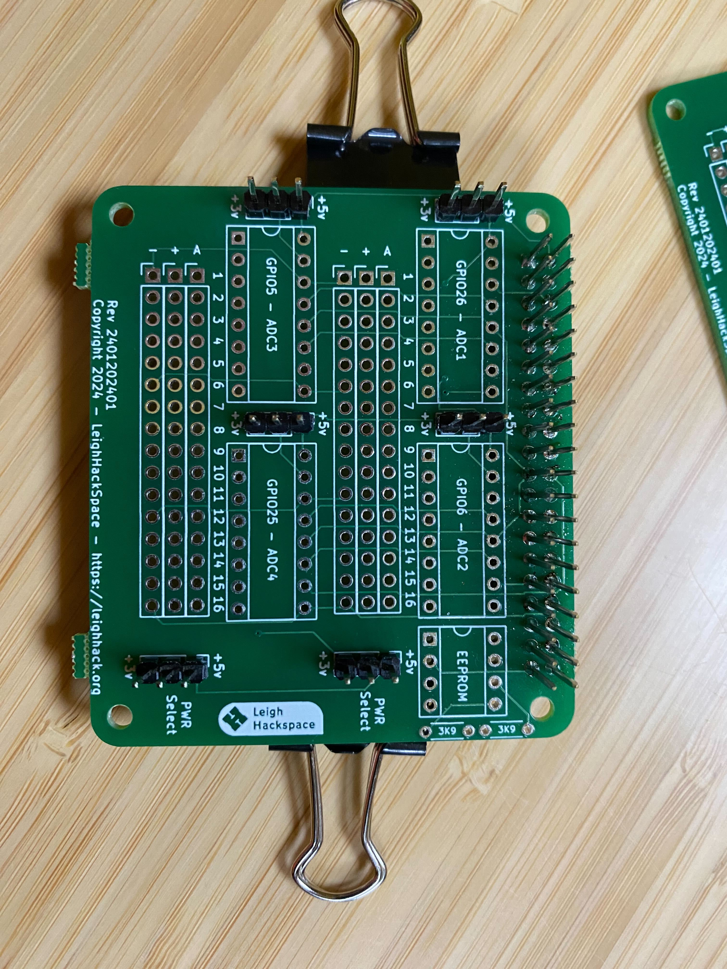
Next was trying to figure out how to make all the connectors straight. Single line headers are somewhat fiddly to get straight, common techniques are solder one into place, while holding then do the rest. As I had several blanks it was easier to make a PCB sandwich so holding them in place with small bull dog clips.
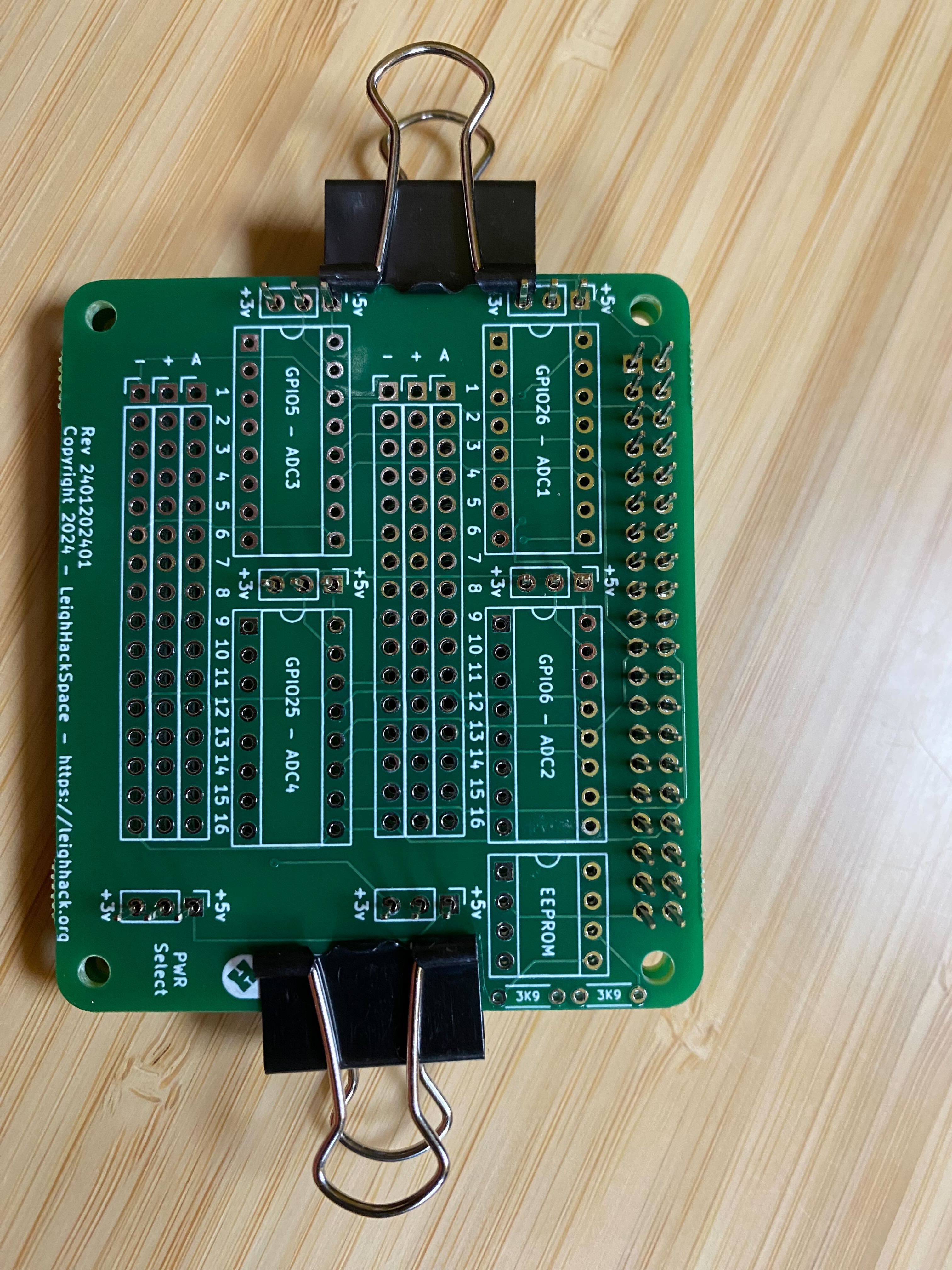
You can see in the picture all the headers are straight so I used this technique for adding in the IC holders and completed the PCB soldering quite quickly.
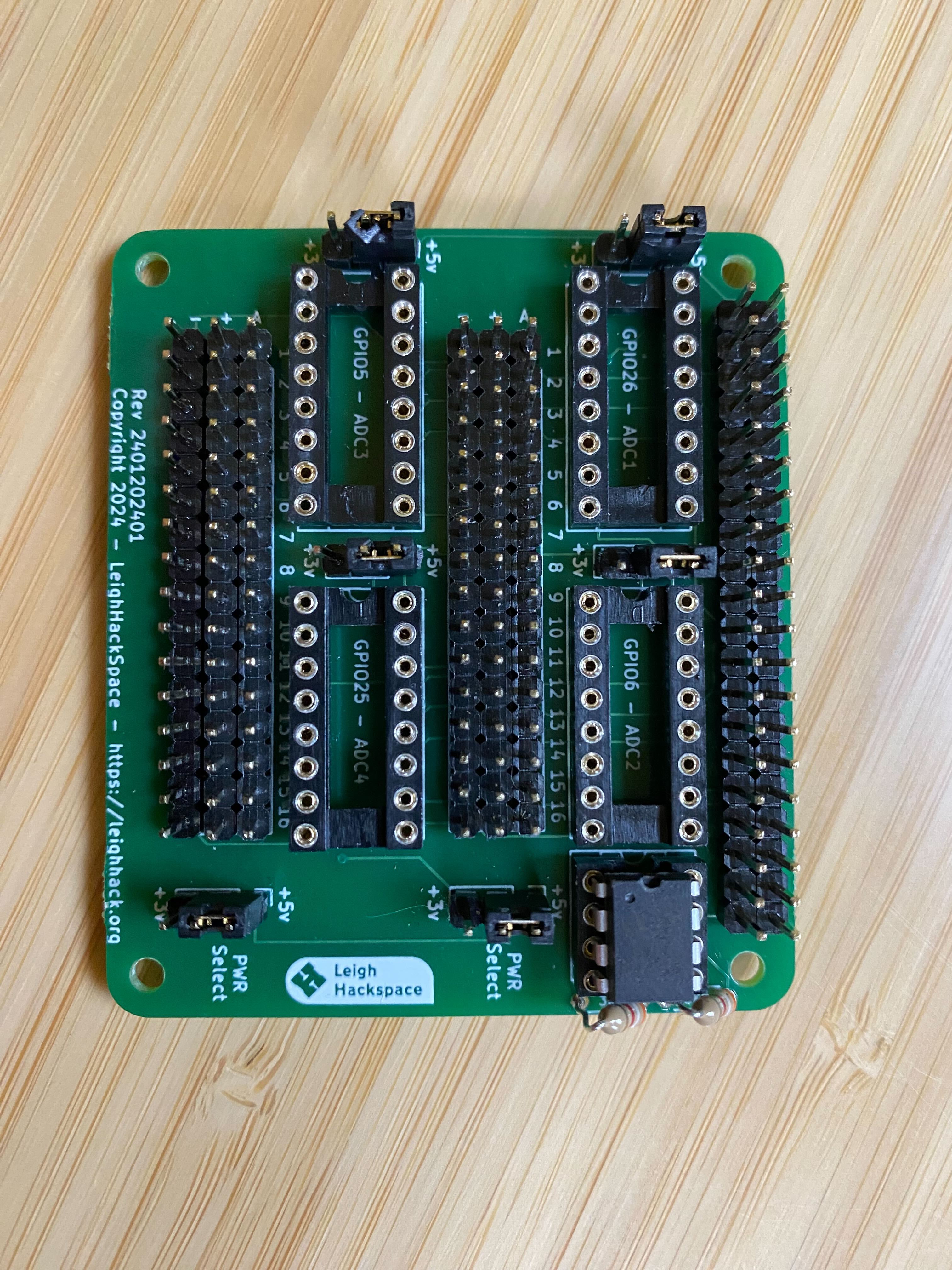
All the connectors, sockets and resistors in place with an EEPROM ready for testing. It provided the same results as the breadboard prototype so I knew it was working for the EEPROM at least, and testing each location I found the moisture sensor worked as needed.
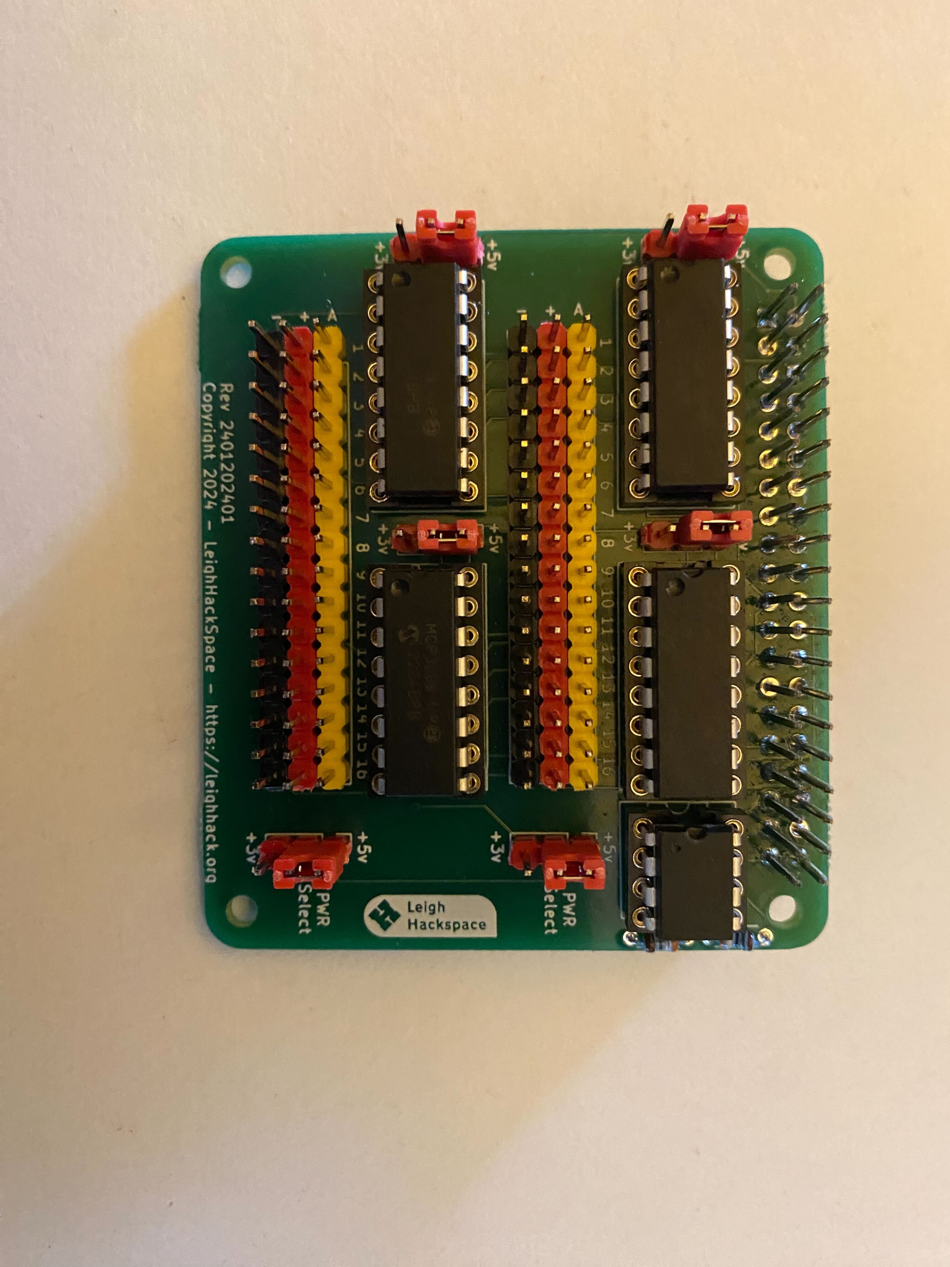
The design worked and I was happy with it, however I also thought it was somewhat hard to determine the direction of connectors (they are marked on the board), so I went one step further and bought some coloured connectors.
As you can see this is much more appealing and make is significantly easier to see the connection orientation and what the jumpers are for. I used red for positive, black for negative and yellow for signal. I matched the orientation to the sensor I had.
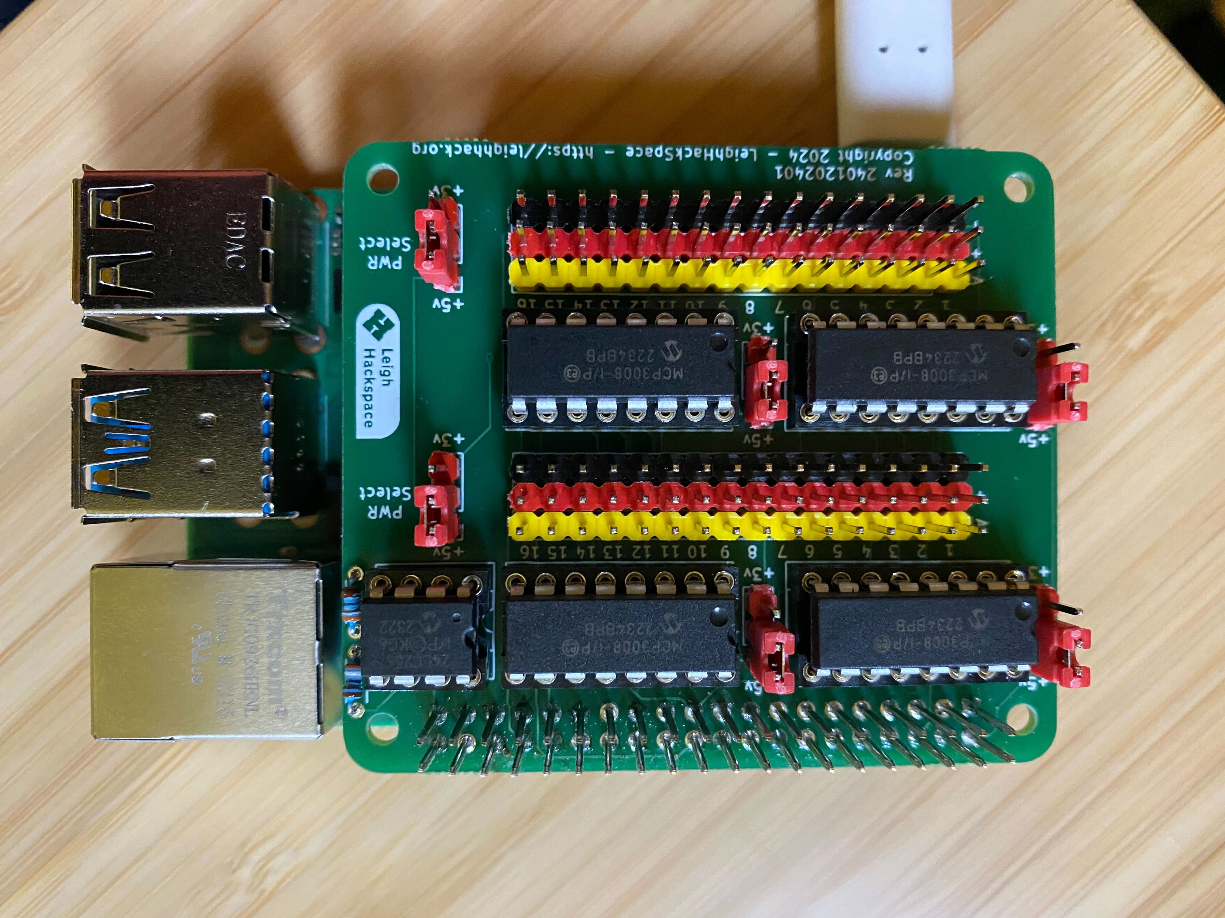
When the Hat is on the Raspberry PI it looks nice and compact ready to be used.
This little project helped me learn quite a bit about the Raspberry PI and how relatively straight forward it is to build something for it. I am working on a couple of new HATs for the next part of my hydroponics set up so will post what they involve when they are done.
Leigh Hackspace is open to all.
Being a member gives you access to our space, tools, and community.