
This is a post by Andrew K.
Posted Wednesday, August 21, 2024
Building a solution to make them flash!
This is a post by Andrew K.
Posted Wednesday, August 21, 2024
I wanted to understand how to make WS2812 LEDs work but also within the Hackspace I found some PICs. I had used something similar many years ago, but this was a completely new learning curve!
There are many many write ups about how 2812 LEDs work, so rather cover much of that I will just outline the basics to get things going.
The WS2812B DataSheet outlines the timings, but to make life easier the basics are as follows :
A simple bit shift register configuration , each LED can have 3 colours, order as green, red and blue. Each colour has 8 bits for brightness, so one byte.
In order to send the correct configuration the following timings apply :
A total of 1us(1000ns) per bit should be used, but see the observation below.
To send a 0, a signal should be held high for between 0.250us (250ns) and 0.550us (550ns), and then low for between 0.700us(700ns) and 1us (1000ns) To send a 1, a signal should be held high for between 0.650us (650ns) and 0.950us (950ns), and then low for between 0.300us(300ns) and 0.450us (450ns)
In order for the LEDs to show the applied configuration the signal should be held low for ~50us.
An observation that can be made is the low part of the signal can be much longer than the specification as it will only reset (so show the LED configuration) with a long delay.
To make one LED show GREEN, the following would be sent, with the correct timing.
1 1 1 1 1 1 1 1 0 0 0 0 0 0 0 0 0 0 0 0 0 0 0 0 <50us>
So 3 bytes, then a delay.
Seems simple right ?
I found some interesting development tools in the Hackspace and decided to go down the route of attempting to use them.

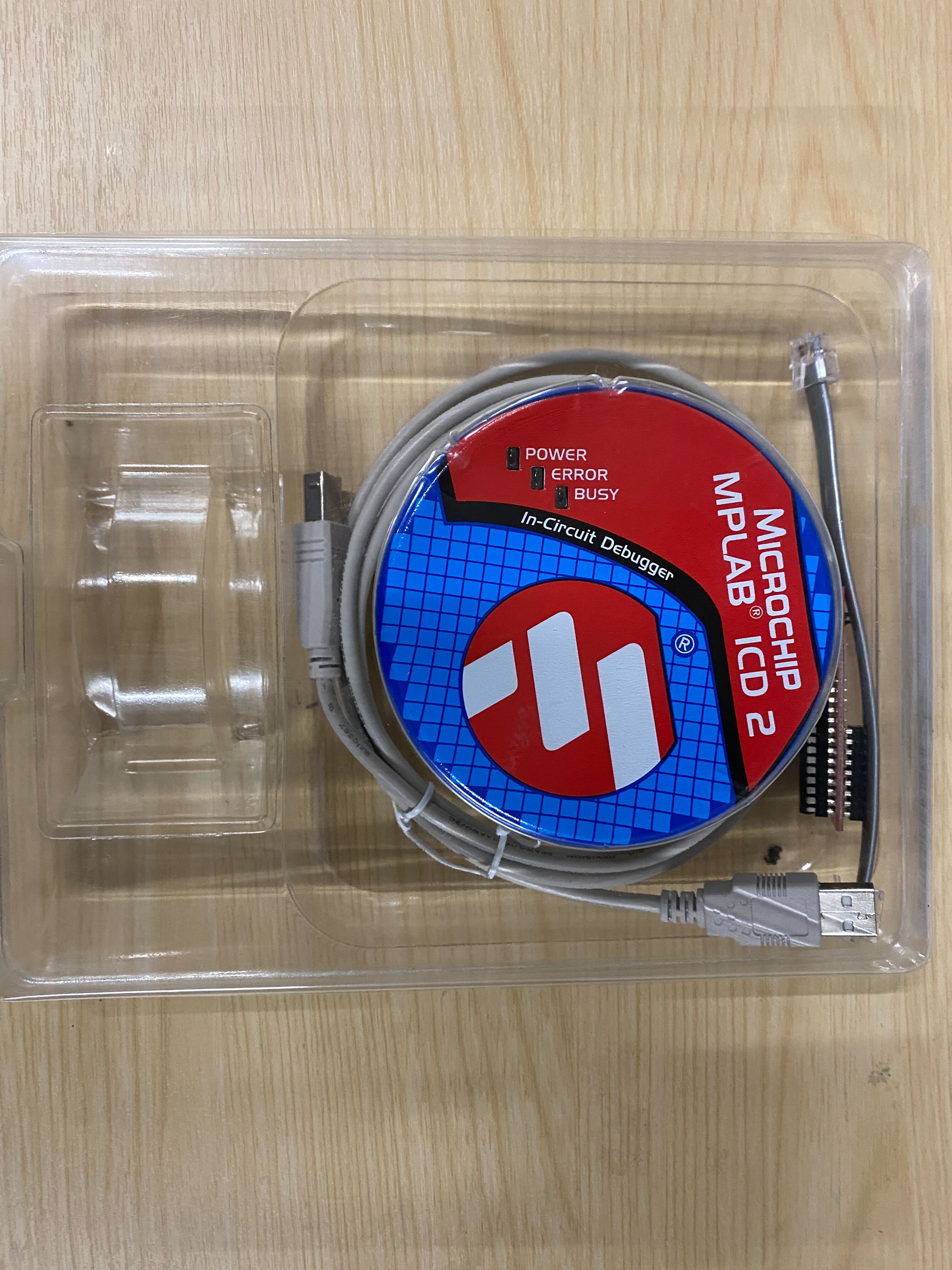
This was immediately hit by a brick wall. The PIC programmer is now considered so old it is no longer supported by any of the actual development tools. I could install Windows XP and get it working but that brings many more problems than I wanted.
I decided to get a PIC Kit 5 programmer, and as it happens they were on sale so 1/2 price, but still £70, at the time of writing. I am interested in doing some other projects, so worth the investment. If anyone at the HackSpace would like to use it, certainly available as needed.

You can also get a slightly different approach using a programmer from here USBProg2
The PIC Kit programmer does integrate seamlessly into all the PIC IDE tools, whereas the USBProg2 is very manual, but can still use the output from the PIC IDE tools, so the choice is to the reader.
I installed MPLAB X IDE which was a little painful as there was some random ‘free’ license I had to get and then the tool asked if other elements needed to be installed. I am not going through the installation of this. I discovered lots and lots of YouTube/Maker Space tutorials on it which is for the reader to go through.
It did recognize my PIC Kit 5 which is now has a selected programmer.
One element of setting up the programmer that does warrant mentioning is the cabling that comes with it is poor. I have put together some breadboard jumper cables and a cable tie to keep it neat. You can buy and additional interface but at the time of writing was more than the programmer which seems odd.
I ended up with
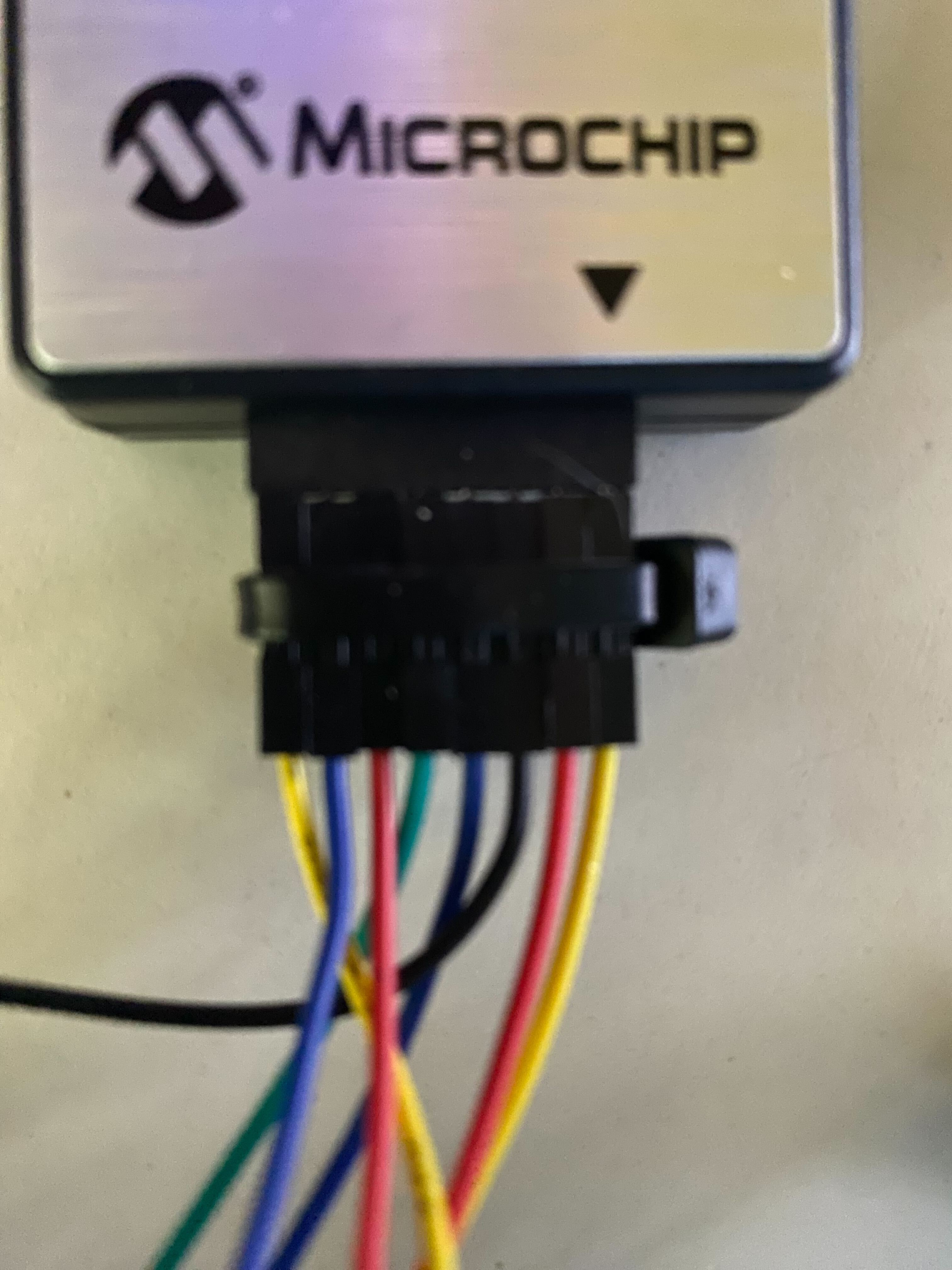
It is a little hackey and I may do something better in the future but for my purposes right now, works!
After a little bit of research I decided to use a PIC16F1613. It is a relatively simple part and has all the functionality needed to get things going quickly. It has a built in clock, 16k of programmable space, 2k of RAM and perfectly capable of doing what I wanted.
When I set up the MPLab X IDE with the part I ended up with a configuration screen as follows
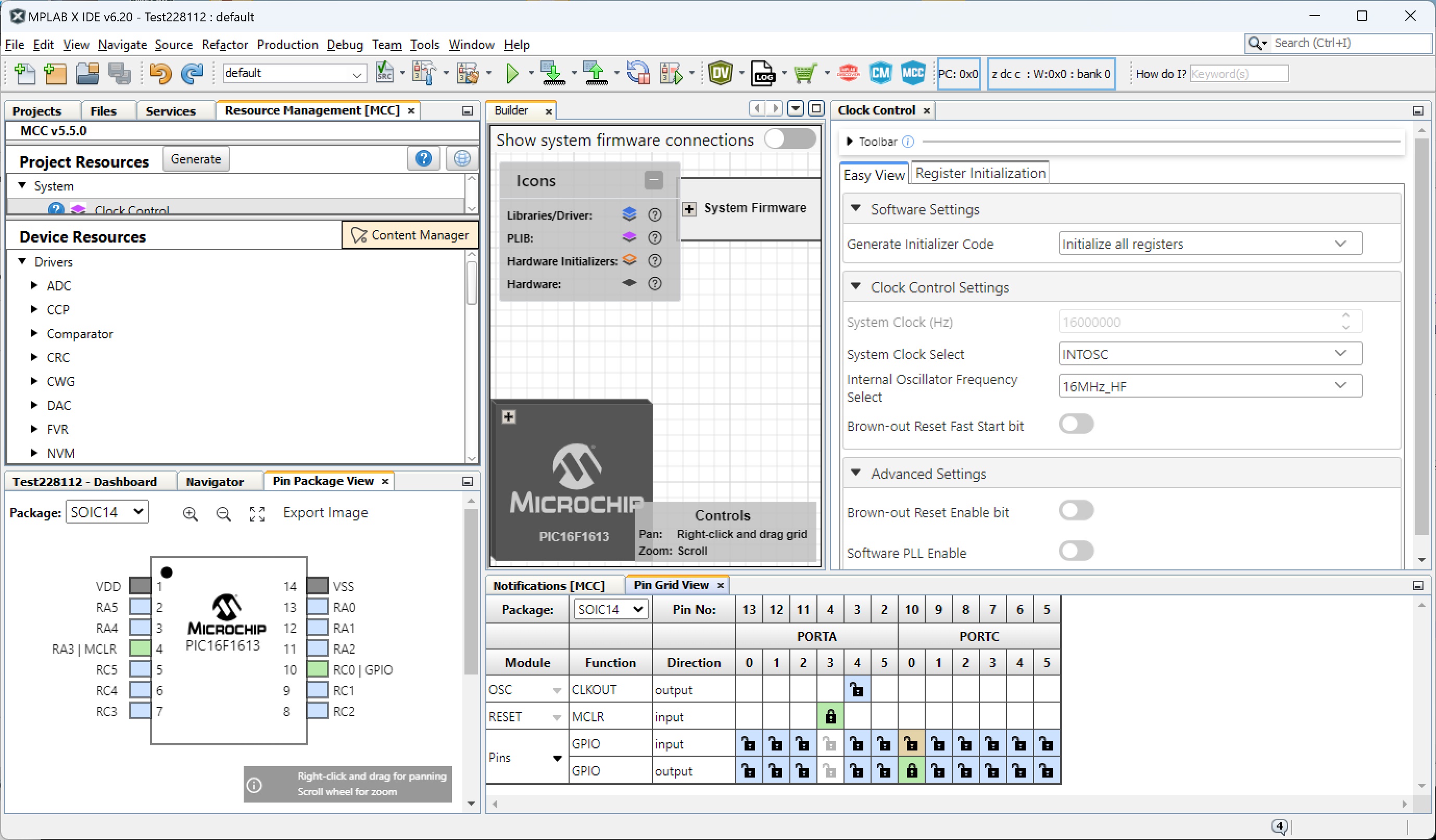
As you can see from the screen shot above, the internal clock is set to 16Mhz and I have set RC0 as an output pin. You do need to be careful with the PIN selection as some of the RA pins are needed for programming so staying away from them makes life much easier. I can leave the programmer connected while testing the output!
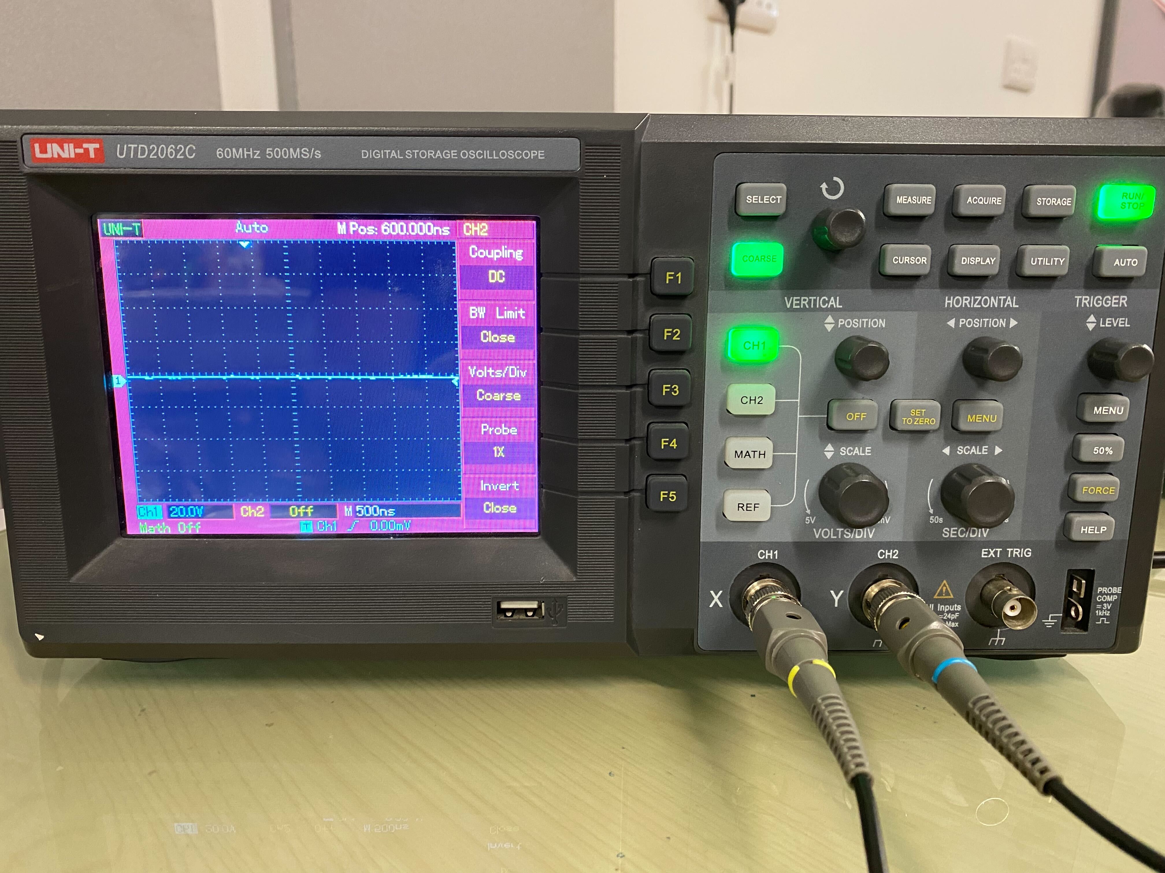
In order to figured out what we need to do with the PIC I used an Oscilloscope and connected it to the output of the PIC (pin 10/RC0).
The scope was a UTD2026C as pictured.
The default code created by the MPLAB X IDE for a new project includes a file called main.c. In this file there is a function called main(void). It is shown below
int main(void)
{
    SYSTEM_Initialize();
}
There may be other lines within your output, but should be commented out and be grey.
In order to toggle the output pin on and off the following code can be used
LATCbits.LATC0 = 0;
If you set it to 0, the output is off, if you set it to 1, the output is on.
To determine how fast we can toggle the pin on/off we first need to add some code to the main(void) so it would become
int main(void)
{
    SYSTEM_Initialize();
    while (1)
    {
        LATCbits.LATC0 = 1;
        LATCbits.LATC0 = 0;
    }
}
By the default the pin is off, so we first enable the output and then disable the output, the PIC then just does this continuously.
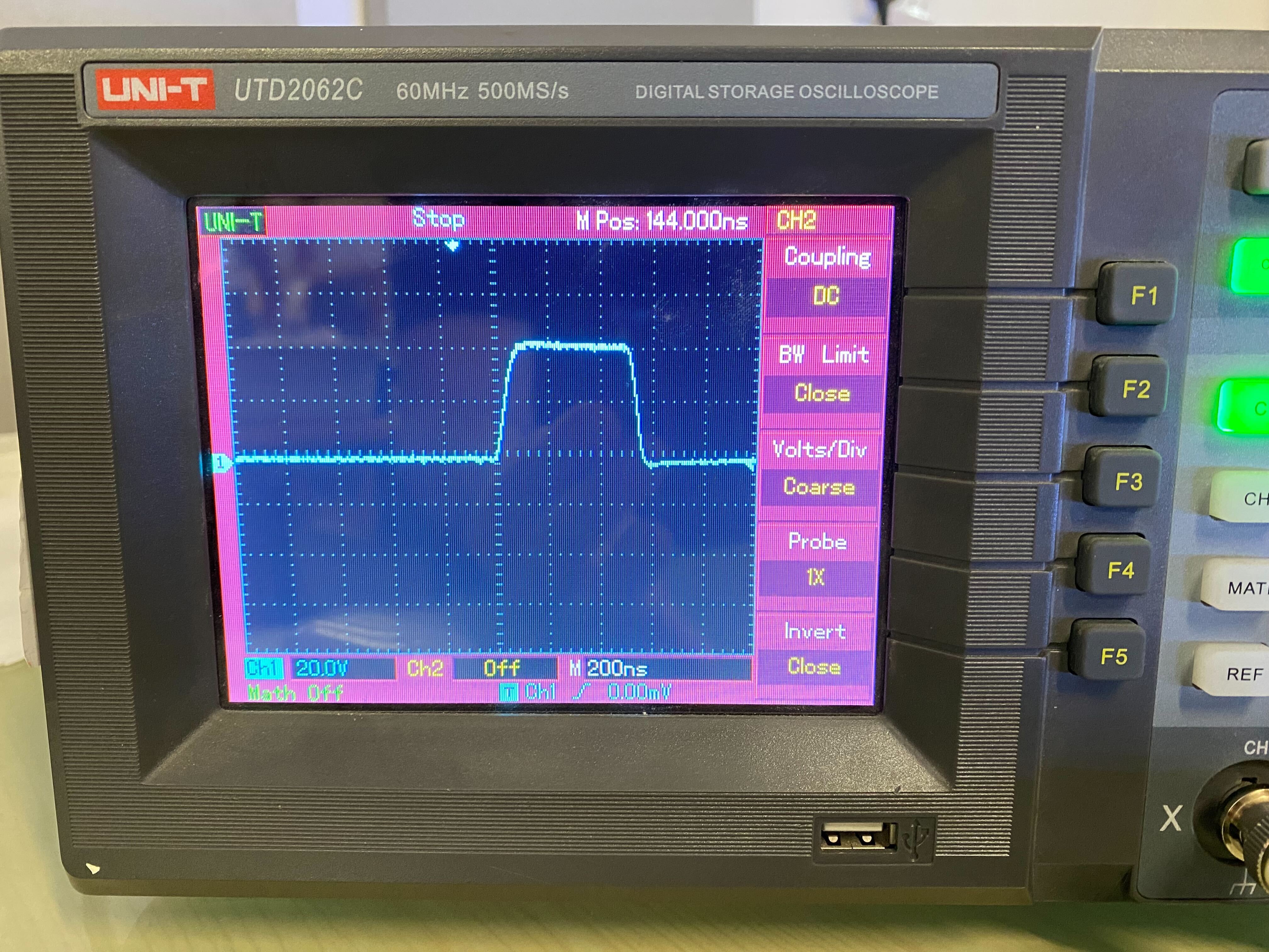
The output from the Oscilloscope is shown
With the scope set to 200ns per segment you can see the rise/fall of the output is ~300ns. This is immediately within the timing for sending a 0. However we also need to look at the gap to the next rise/fall to make sure we are not exceeding 50us.
The gap between two rise and falls is 2000ns (2us) so does fall within our 50us delay requirement.
We now need to determine how to keep the pin high for longer, as need to be able to send a longer pulse for setting a 1. There are various ways to do this, however the simplest is to just set the pin high again, so our code now changes to
int main(void)
{
    SYSTEM_Initialize();
    while (1)
    {
        LATCbits.LATC0 = 1;
        LATCbits.LATC0 = 1;
        LATCbits.LATC0 = 0;
    }
}
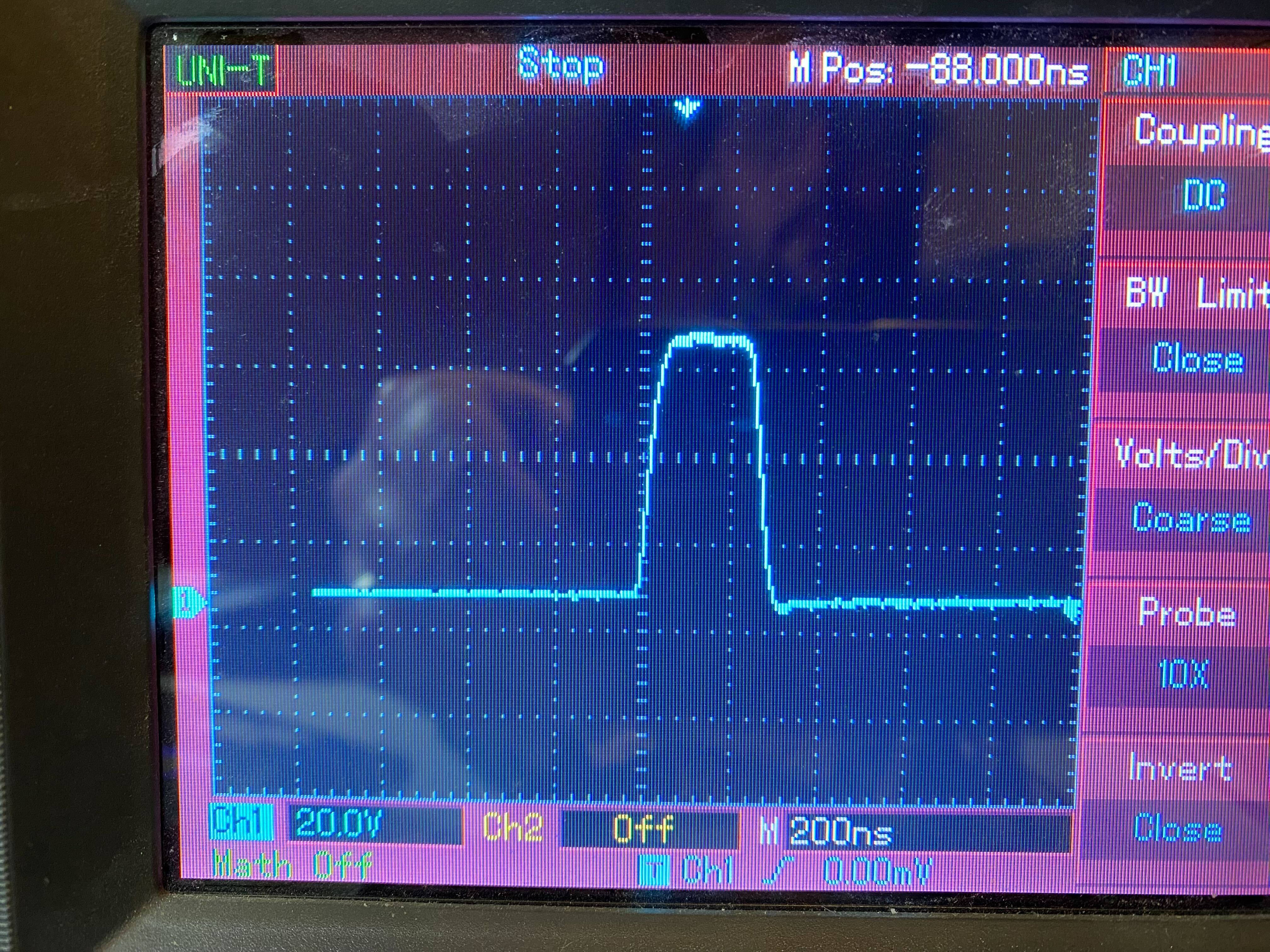
At the clock rate is set to 16Mhz, per cycle for the PIC is approximately 62.5ns per instruction.
This is really close and gives ~500ns. We need at least 550ns to make sure we are within tolerance of the specifications.
We can see per setting the pin to high, we have added ~200ns, which suggests 3 instructions are being used per setting, even though the value has not changed.
Then we changed to
int main(void)
{
    SYSTEM_Initialize();
	while (1)
	{
		LATCbits.LATC0 = 1;
		LATCbits.LATC0 = 1;
		LATCbits.LATC0 = 1;
		LATCbits.LATC0 = 0;
	}
}
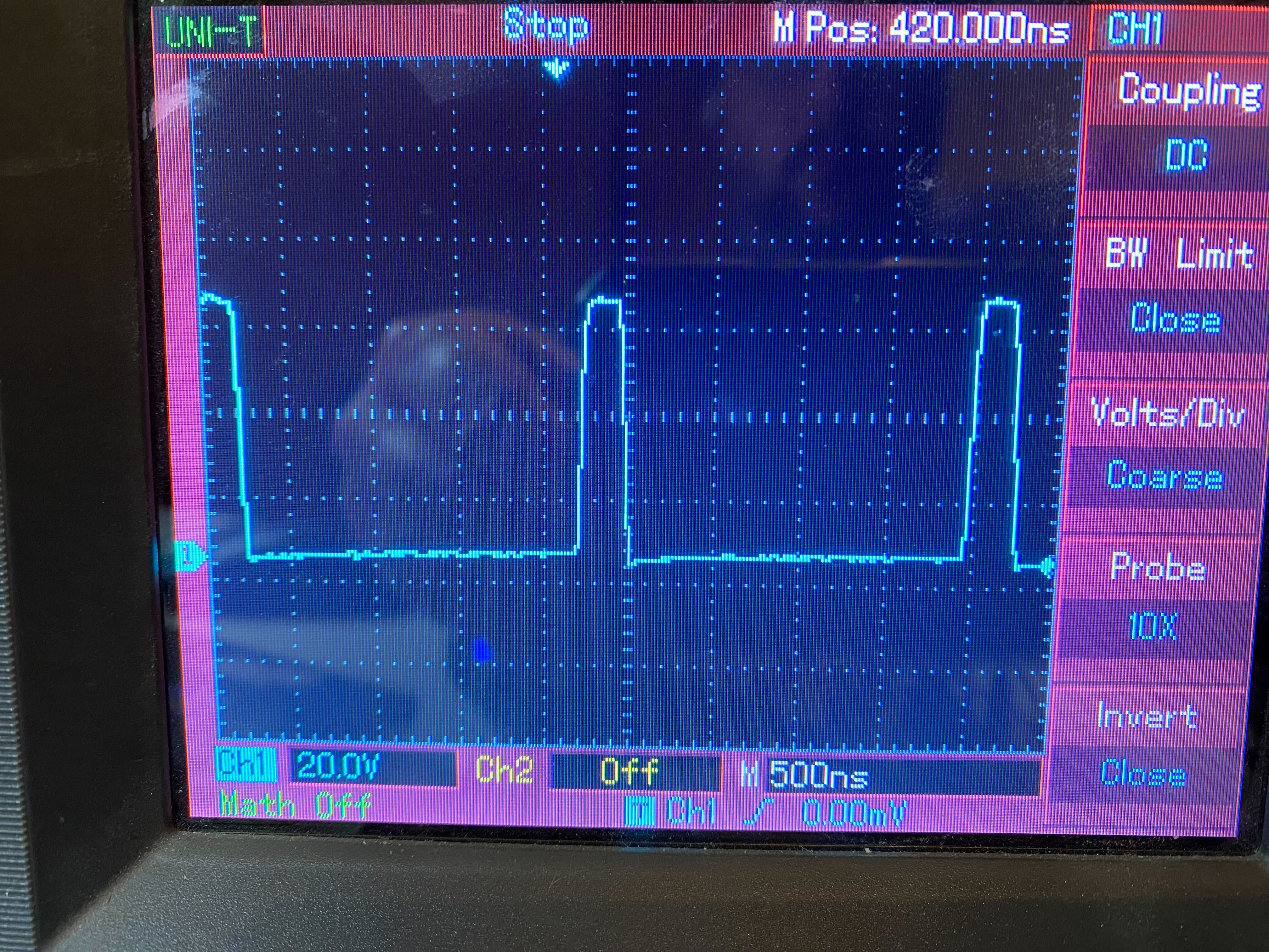
This provided the output we need for a 1 bit set, it is approx 750ns.
Now we have both ways to set for a long (one) and a short(zero), for the output. You can see on the above image the edge of the previous long pulse, and our gap between rise and fall has increased to 2.5us(2500ns), so something we may need to be aware of later.
To make life much simpler to set these I created two functions (placed before the main(void) function).
void longPulse(void)
{
    LATCbits.LATC0 = 1;
    LATCbits.LATC0 = 1;
    LATCbits.LATC0 = 1;
    LATCbits.LATC0 = 0;
}

void shortPulse(void)
{
    LATCbits.LATC0 = 1;
    LATCbits.LATC0 = 0;
}
Now it appears we have the timing correct we need to try and set the different colours for the first LED. It is important to remember that the LED colours are green, red, blue, so we will try them in order one at a time. This also sets a very long delay of 50ms, well beyond the 50us required in order to trigger the configuration to be delayed.
int main(void)
{
    SYSTEM_Initialize();
	while (1)
	{
		// Green 8 bits set to 1
		longPulse();longPulse();longPulse();longPulse();
		longPulse();longPulse();longPulse();longPulse();

		// Red all bits set to 0
		shortPulse();shortPulse();shortPulse();shortPulse();
		shortPulse();shortPulse();shortPulse();shortPulse();

		// Blue all bits set to 0
		shortPulse();shortPulse();shortPulse();shortPulse();
		shortPulse();shortPulse();shortPulse();shortPulse();

		__delay_ms(50);
	}
}
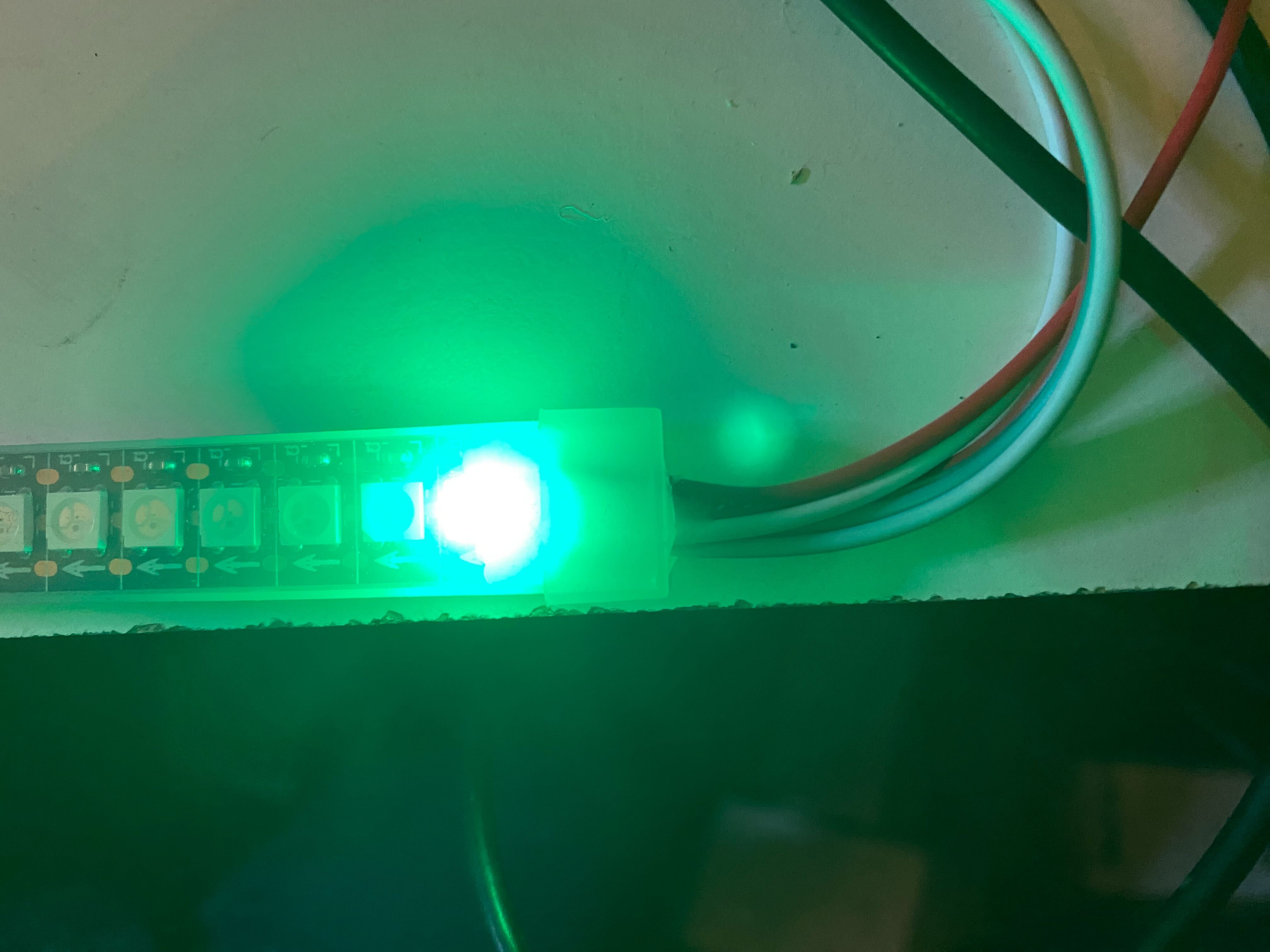
This then gives us the output on a LED of green
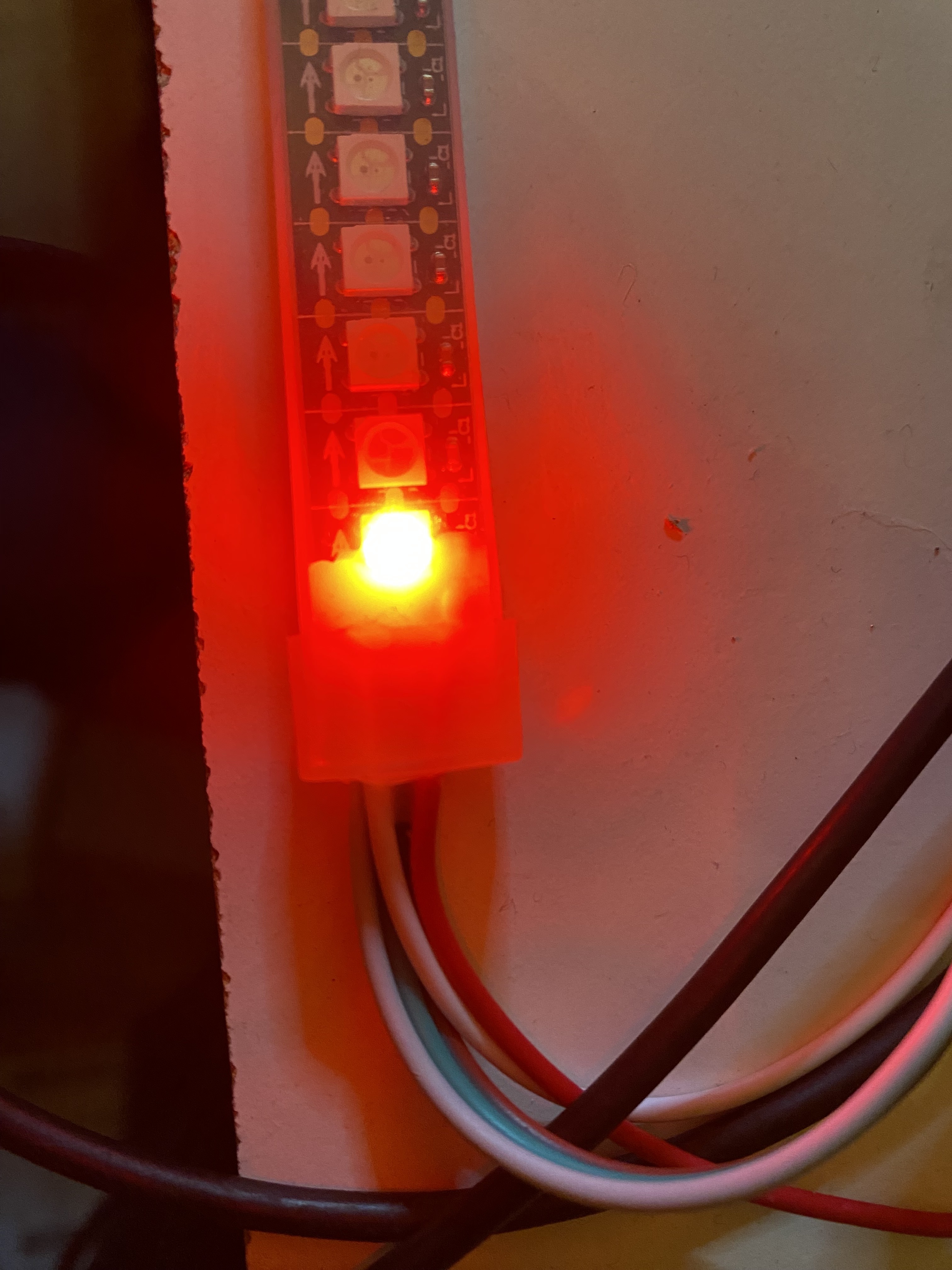
I then cycled through the different options, so red
int main(void)
{
    SYSTEM_Initialize();
	while (1)
	{
		// Green 8 bits set to 0
		shortPulse();shortPulse();shortPulse();shortPulse();
		shortPulse();shortPulse();shortPulse();shortPulse();

		// Red all bits set to 1
		longPulse();longPulse();longPulse();longPulse();
		longPulse();longPulse();longPulse();longPulse();

		// Blue all bits set to 0
		shortPulse();shortPulse();shortPulse();shortPulse();
		shortPulse();shortPulse();shortPulse();shortPulse();

		__delay_ms(50);
	}
}
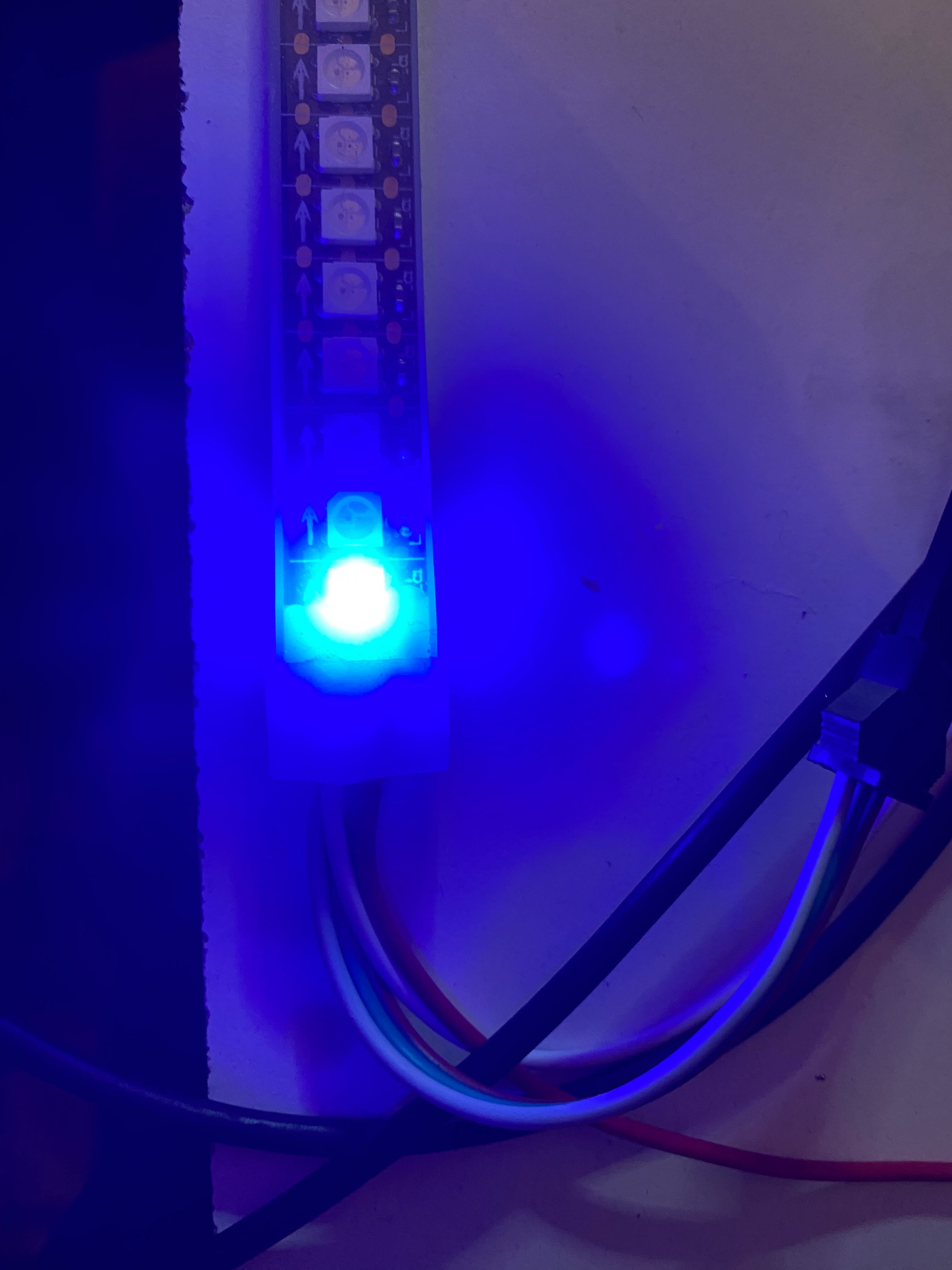
Now finally blue
int main(void)
{
    SYSTEM_Initialize();
	while (1)
	{
		// Green 8 bits set to 0
		shortPulse();shortPulse();shortPulse();shortPulse();
		shortPulse();shortPulse();shortPulse();shortPulse();

		// Red all bits set to 0
		shortPulse();shortPulse();shortPulse();shortPulse();
		shortPulse();shortPulse();shortPulse();shortPulse();

		// Blue all bits set to 1
		longPulse();longPulse();longPulse();longPulse();
		longPulse();longPulse();longPulse();longPulse();

		__delay_ms(50);
	}
}
You can experiment with the bits being sent for the intensity of the colour and you should find the first bit is the high value and last bit is the low value in order thus,
128 64 32 16 8 4 2 1 - bit values of a byte
Pulse order sent
1 0 0 0 0 0 0 0
This would give a half intensity colour for whichever colour was being set, so you can now create a function to send byte values rather than just single pulses.
void sendsingle_byte(unsigned char byte)
{
    if ( byte & 0b10000000) { longPulse(); }
    else { shortPulse(); }
    if ( byte & 0b01000000) { longPulse(); }
    else { shortPulse(); }
    if ( byte & 0b00100000) { longPulse(); }
    else { shortPulse(); }
    if ( byte & 0b00010000) { longPulse(); }
    else { shortPulse(); }
    if ( byte & 0b00001000) { longPulse(); }
    else { shortPulse(); }
    if ( byte & 0b00000100) { longPulse(); }
    else { shortPulse(); }
    if ( byte & 0b00000010) { longPulse(); }
    else { shortPulse(); }
    if ( byte & 0b00000001) { longPulse(); }
    else { shortPulse(); }
}
This function should be placed before the longPulse() and shortPulse() in your main.c code.
It uses a binary mask ( &0b prefix ) to check against each bit in the byte provided into the function and then sends either a longPulse() or shortPulse() depending if it is set or not.
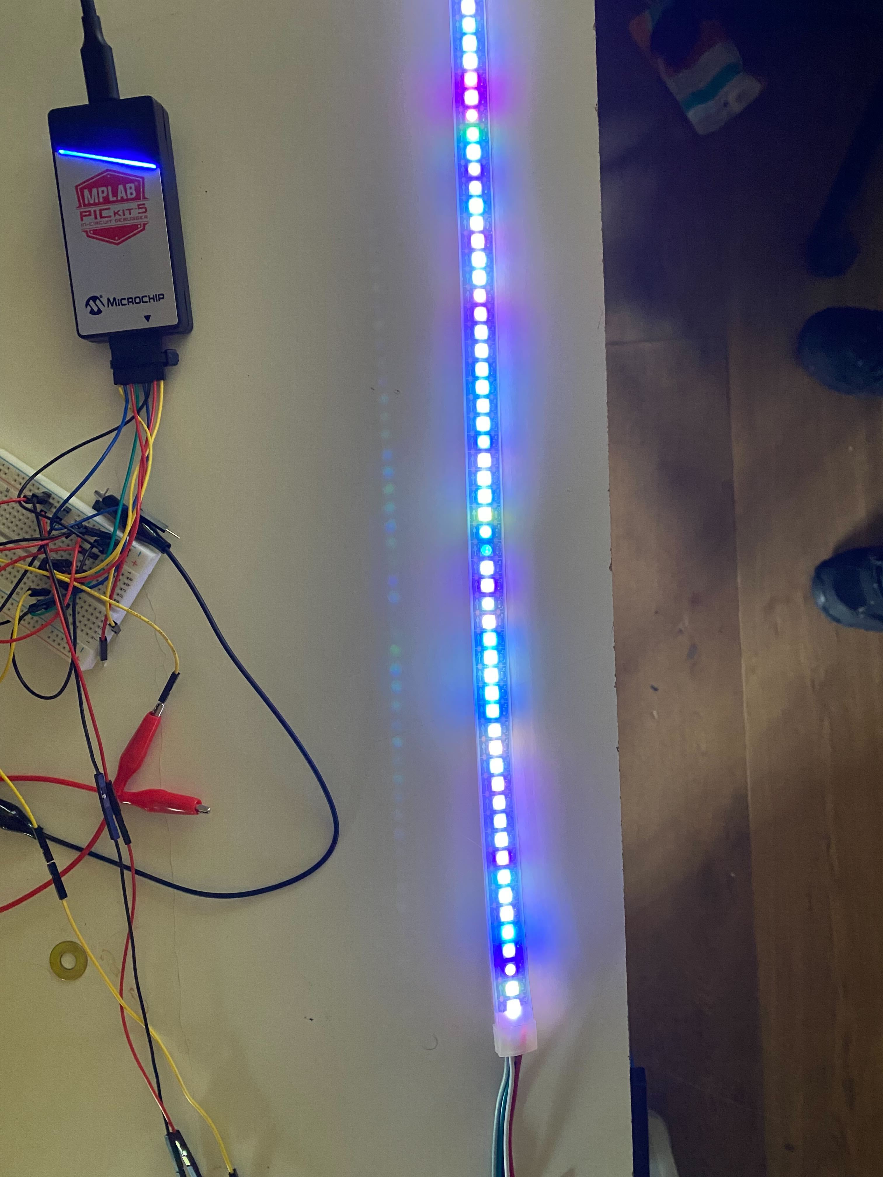
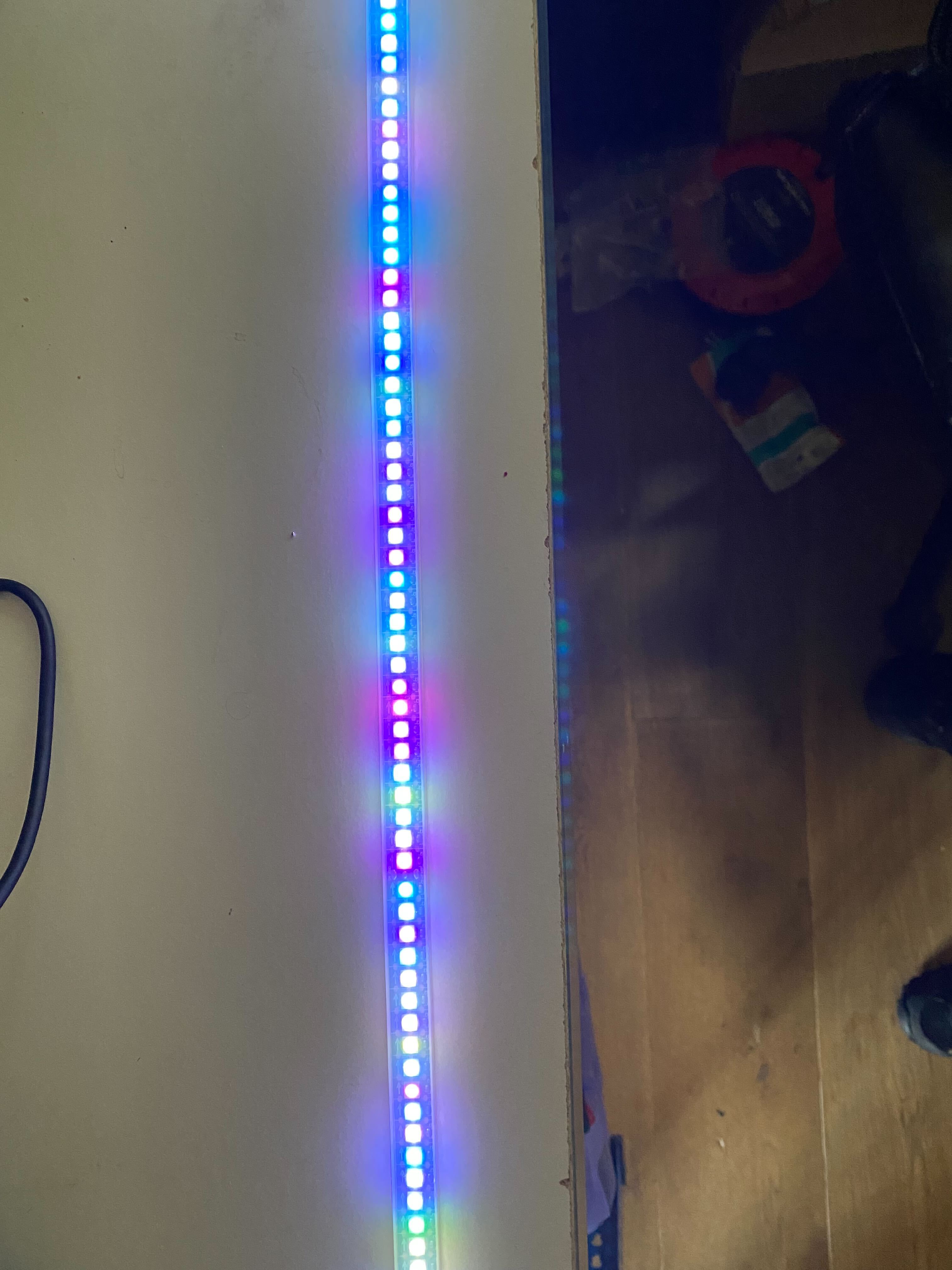
I was then interested in making a 144 LED strip working with different colours. In modern computing you can just use memory and allocate it based on your needs, and in this case would be 3 bytes x 144 which is 432 bytes. However with the PIC chosen it only has 2k of RAM of which most - 1500 bytes - is used when initializing the program and other variables needed.
In order to cope with the lack of memory I decided that a small buffer of 70 bytes would suffice, which is two bytes short of 24 LEDs, which can then be replicated across the number of LEDs required. I did however want to keep as much visual randomness as possible.
The code I came up with was as follows
void longPulse(void)
{
    LATCbits.LATC0 = 1;
    LATCbits.LATC0 = 1;
    LATCbits.LATC0 = 1;
    LATCbits.LATC0 = 0;
}
void shortPulse(void)
{
    LATCbits.LATC0 = 1;
    LATCbits.LATC0 = 0;
}
void sendsingle_byte(unsigned char byte)
{
    if ( byte & 0b10000000) { longPulse(); }
    else { shortPulse(); }
    if ( byte & 0b01000000) { longPulse(); }
    else { shortPulse(); }
    if ( byte & 0b00100000) { longPulse(); }
    else { shortPulse(); }
    if ( byte & 0b00010000) { longPulse(); }
    else { shortPulse(); }
    if ( byte & 0b00001000) { longPulse(); }
    else { shortPulse(); }
    if ( byte & 0b00000100) { longPulse(); }
    else { shortPulse(); }
    if ( byte & 0b00000010) { longPulse(); }
    else { shortPulse(); }
    if ( byte & 0b00000001) { longPulse(); }
    else { shortPulse(); }
}
int main(void)
{
    SYSTEM_Initialize();

	// 144 LEDs in the strip i am using.
    int ledCount = 144;

	// The ledCount in the array to create random values
    int ledCountArrayMem = 70;

	// Total byte send, each LED has 3 bytes, so ledCount multipled by 3
    int ledCountCol = ledCount * 3;

    // Create an array of 70 values for the random values.
    // This should be an odd number, NOT divisible by 3.
    // This array could be much smaller however does reduce how
    // 'random' the LEDs look.
    char ledCountArray[70];

    // Array position counter
    int d = 0;

    // init srand
    srand(40);

    // clear all LEDs to no value.
    for ( int o = 0 ; o < ledCount*3; o++)
    {
       sendsingle_byte( 0b00000000 );
    }
    __delay_ms(50);

    while(1)
    {
        // Creating random values is slow, so creating them into
        // an array first before we send them out keeps the LEDs
        // from thinking there is a timeout to display.
        for ( int l = 0 ; l < ledCountArrayMem ; l++ )
        {
           // I used a mask of 0x0f to reduce the intensity of the LED brightness.
           // If you change this, say of 0xff, two things will happen
           // 1 - the LEDs will be MUCH brighter
           // 2 - your power usage will increase
           ledCountArray[(l)] = (rand()&0x0f);
        }

        // Now we loop through all the LED bytes needed to be sent
        // Simple count from 0 to the number of LEDs multipled by 3
        // as set above.
        for ( int o = 0 ; o < ledCountCol; o++)
        {
            sendsingle_byte( ledCountArray[d] );
            d++;
            // As the array is an odd number, not divisible by 3
            // when it reaches the end, it is not a complete LED value
            // so cycles back to the start of the array, so the random
            // values are different for the next block of LEDs to be shown.
            if ( d == ledCountArrayMem )
               d = 0;
        }
        __delay_ms(50);
    }
}
This code uses a 70 byte array to handle any number of LEDs, and it does give the impression of randomness. As the routine does an odd size array, not divisible by 3, it tries to ensure no obvious repeating pattern.
The output can be seen here
As part of programming the LEDs I have looked at various patterns and one more for anyone to try out is a simple back and forth single LED, making it blue.
void longPulse(void)
{
    LATCbits.LATC0 = 1;
    LATCbits.LATC0 = 1;
    LATCbits.LATC0 = 1;
    LATCbits.LATC0 = 0;
}
void shortPulse(void)
{
    LATCbits.LATC0 = 1;
    LATCbits.LATC0 = 0;
}
void sendsingle_byte(unsigned char byte)
{
    if ( byte & 0b10000000) { longPulse(); }
    else { shortPulse(); }
    if ( byte & 0b01000000) { longPulse(); }
    else { shortPulse(); }
    if ( byte & 0b00100000) { longPulse(); }
    else { shortPulse(); }
    if ( byte & 0b00010000) { longPulse(); }
    else { shortPulse(); }
    if ( byte & 0b00001000) { longPulse(); }
    else { shortPulse(); }
    if ( byte & 0b00000100) { longPulse(); }
    else { shortPulse(); }
    if ( byte & 0b00000010) { longPulse(); }
    else { shortPulse(); }
    if ( byte & 0b00000001) { longPulse(); }
    else { shortPulse(); }
}
int main(void)
{
    SYSTEM_Initialize();

    int ledCount = 144;
    int liPos = 0 ;
    int currPos = 0;

    // clear all LEDs to no value.
    for ( int o = 0 ; o < ledCount*3; o++)
    {
       sendsingle_byte( 0b00000000 );
    }
    __delay_ms(50);

     while (1)
    {
        liPos = 0;
        for ( int t = 0 ; t < ledCount*2; t++)
        {
            for ( int led = 0 ; led < ledCount ; led ++ )
            {
                if ( led == currPos )
                {
                    // Send a blue colour at the correct position.
                    ws_send_byte( 0b00000000 );
                    ws_send_byte( 0b00000000 );
                    ws_send_byte( 0x34 );
                }
                else
                {
                    // Reset the LED when not at the correct position.
                    ws_send_byte( 0b00000000 );
                    ws_send_byte( 0b00000000 );
                    ws_send_byte( 0b00000000 );
                }
            }
            liPos++;
            currPos =  ((liPos + ledCount) % (ledCount*2))  - ledCount ;

            // Invert the position to track back and forth.
            if ( currPos < 0 )
               currPos = currPos * -1;

            __delay_us(100);
        }
    }
}
As I was going through all of this, learning lots and lots of interesting things, from PICs, to the MPLAB X IDE, and of course the 2812 LEDs, someone at the Hackspace pointed out a much simpler, far more developed way.
Using an ESP32 with WLED or FAST LED libraries. All the timing, patterns, control interface has all been done and very simple to get going.
I am going to continue to learn about PICs, as they do have their place, single standalone projects, very cheap and incredibly low power.
Leigh Hackspace is open to all.
Being a member gives you access to our space, tools, and community.